How an RTO Works
Designed for high air flow volumes and low VOC process streams, regenerative thermal oxidizers can achieve high thermal recovery efficiencies (95%+) & destruction efficiencies (99%+ DRE). They also possess more moving parts and often require more inspections and maintenance compared to other types of air pollution control systems.
What is a Regenerative Thermal Oxidizer (RTO)?
A Regenerative Thermal Oxidizer (RTO) is a popular, proven type of air pollution control equipment used to destroy Volatile Organic Compounds (VOCs) and Hazardous Air Pollutants (HAPs) found in industrial exhaust streams. They are best suited for applications with high waste stream flow rates (5,000+ SCFM), low VOC concentrations, and minimal particulate.
In the simplest terms, Regenerative Thermal Oxidizers operate at very high temperatures (typically 1500 degrees F or higher) to clean pollutants from process exhaust. Ceramic media beds in the RTO unit capture up to 95% of the heat from the exiting clean air before exhausting the air to the atmosphere. The ceramic media beds then release this heat to pre-treat incoming dirty air before the air enters the RTO’s combustion chamber.
A standard three-tower RTO design employs one tower to heat the incoming air, another tower to absorb waste heat from the exiting air, and a third tower to purge air. The purged air is then sent through the combustion chamber to remove remaining VOCs to help ensure clean air is released into the atmosphere.
Sometimes air volumes are so high – as in many painting and coating applications – they would require a huge, cost-prohibitive RTO system. In these cases, when the airflow is at or near ambient temperatures, a Zeolite Concentrator can be added upstream of the oxidizer to condense fuel-abundant VOCs and reduce air volumes, allowing for a smaller, less expensive RTO.
How a Multi-Chamber RTO Works, Step by Step
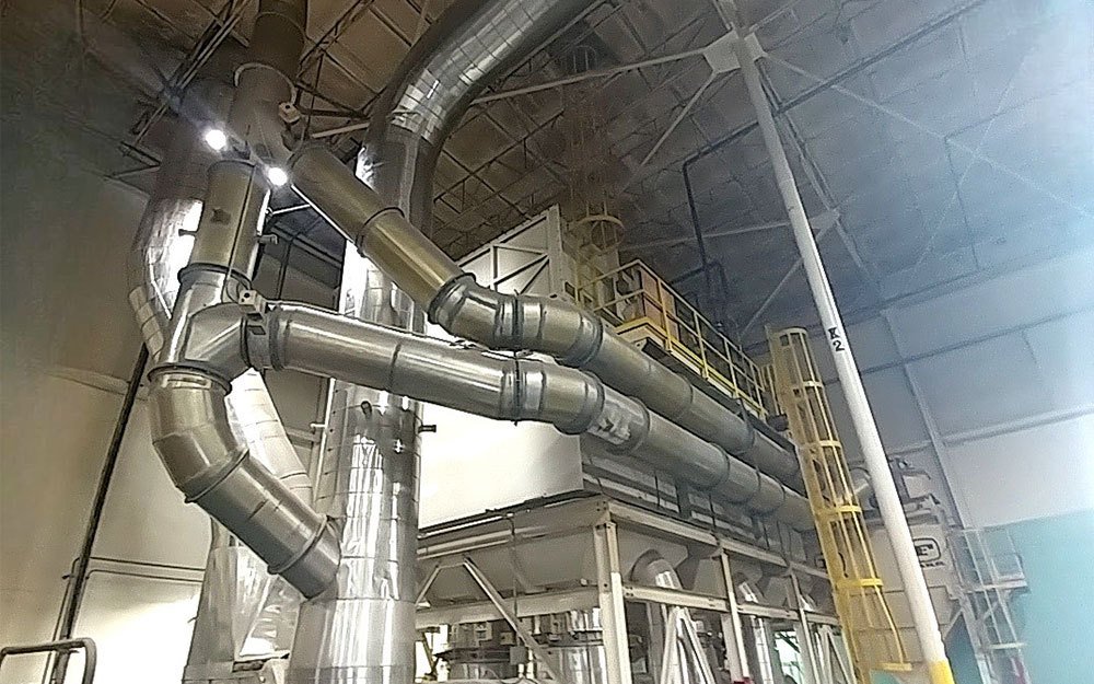
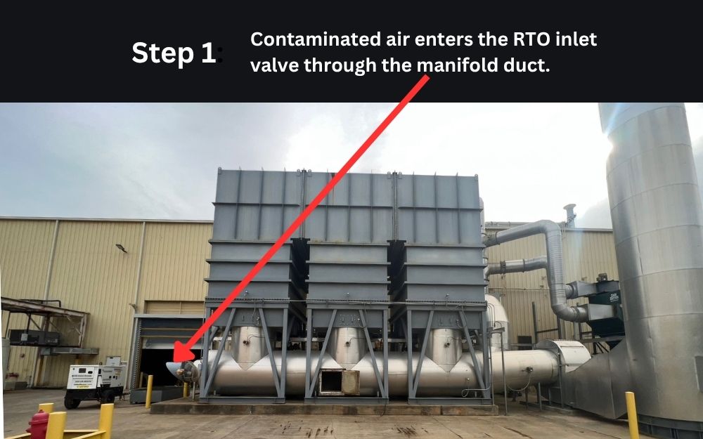
- Process stream (waste stream) is drawn into the oxidizer’s Inlet Manifold by the System Fan through a set of inlet ducts.
- Valves direct the stream up through one bed of the Recovery Chamber filled with ceramic media that has been warmed to temperature.
- Process stream is pre-heated as it travels through the Ceramic Media Bed.
- Process stream enters Combustion Chamber heated by Burner(s) to a Chamber Set Point based on application and pollutants (types of VOCs).
- Pollutants remain in Combustion Chamber for a specified retention time until they are destroyed and converted into water and CO2.
- Process stream enters the other bed of the Recovery Chamber, where the now-purified air releases thermal energy as it passes through the ceramic media bed, warming it.
- Cooled, clean air exits the RTO through Exhaust Stack.
- Flow direction is switched to take advantage of the now warmed-up chamber bed to pre-heat the new incoming waste stream. (Inlet side is now outlet side.)
RTO Costs
The initial capital cost of a regenerative thermal oxidizer varies widely and is dependent on variables including system type, size, and location. Most new RTOs cost more than $100,000 (USD), with larger units costing half a million dollars or more. This does not include installation and commissioning. Key design features that impact capital cost are the exhaust rate and emission point temperature, which affect unit size and ductwork.
Operating costs for a new RTO also vary widely and are dependent on variables including process exhaust temperature, air pollutant type and concentration, system thermal efficiency, system design complexity (i.e., maintenance needs), and electricity and fuel costs. As an RTO ages, many other factors come into play. Also, while peak VOC loads usually govern the design of a new oxidizer, average VOC loads dictate actual operating costs.
Do RTOs Offer the Lowest Cost of Ownership?
Some RTO manufacturers tout that RTOs offer the lowest cost of ownership and the lowest cost of energy costs compared to other air pollution control technologies. This is not always true. Read our article to learn more about these and other common RTO misconceptions.
RTO vs. Thermal Oxidizers: Advantages & Disadvantages
| RTO | Thermal Oxidizer | |
|---|---|---|
| Thermal Efficiency | 95% | 70% - can be higher if incorporates secondary heat recovery due to high exhaust temperatures |
| Destruction Efficiency Range (DRE) | Typical regenerative incinerator design efficiencies range from 95-99% for RTO systems (Ref: EPA) | Typical recuperative incinerator design efficiencies range from 98 to 99.9999% and above (Ref: EPA) |
| Additional System Requirements to Achieve up to 99% DRE | Typically a standard two-chamber RTO attains up to 97% DRE. Using a third chamber and valves – or additional dampers, fans, and “puff chambers”, complicated valve sequencing, and added operational complexities – up to 99% DRE can be achieved | No additional components are required to attain 99.9% DRE |
| Operating Reactor Temperature Range | An RTO uses natural gas to heat entering waste gas to approx. 760°C to 820°C (1400°F to 1500°F), however, it is capable of operating up to 1100°C (2000°F) for those cases where maximum destruction is necessary (Ref: EPA) | Thermal destruction of most organic compounds occurs between 590°C and 650°C (1100°F and 1200°F). Most hazardous waste incinerators are operated at 980°C to 1200°C (1800°F – 2200°F) to ensure nearly complete destruction of the organics in the waste (Ref: EPA) |
| Effect of Particulate Matter or Condensable Compounds Entering System | Prolonged exposure to small amounts of particulates or condensables can accumulate on the “cold face” or within the ceramic bed, raising system pressure drop and increasing fan energy use. “Bake-outs” may provide temporary relief, but over time, deposits can cause irreversible damage. Complete removal is only possible by replacing the ceramic media, which is often needed with little warning. | No additional components are needed to “ride through” a higher VOC concentration. These conditions are more easily avoided in a thermal oxidizer due to its lower thermal efficiency and ability to shed heat more easily. |
| Mechanical Components Not Common to Both Systems | Poppet valves, actuators, solenoids, seals and gaskets; additional dampers and/or fans required to increase DRE to 99%; NGI components; a hydraulic pack or air compressor to power poppet valve actuators; and a regenerative compressed air dryer. Some RTOs also use a complex electronic drive and electric motor and gear box to operate pilot valves. | No additional mechanical components which are not common to both types of systems. |
| Typical Gas Flow Ranges (Process Air Volume) | Typical gas flow rates for regenerative incinerators are 2.4 to 240 sm3/sec (5,000 to 500,000 scfm) (Ref: EPA) | Typical gas flow rates for recuperative incinerators are 0.24 – 24 standard cubic meters per second (sm3/sec) (500 to 50,000 standard cubic feet per minute scfm) (Ref: EPA) |
| On-Stream Reliability | Unlike all other oxidation technologies, RTO systems are highly mechanically intensive systems. RTOs incorporate may additional components not common to other oxidizer designs. This coupled with high impact operation, constant and repetitive pressure changes, and complex sequence of operation significantly impact an RTO’s overall reliability. | Thermal oxidizers are the most proven and reliable method available. Thermal oxidizers operate in a significantly more stable state. There are no constant jarring effects, upsets in flow and pressure, or the addition of numerous mechanical devices not common to other oxidizer systems. |
| Key Disadvantages | Higher initial cost – Complicated installation – Large size and weight – High maintenance demand for moving parts (Ref: EPA) | Even with recuperating waste heat energy, incinerator operating costs can be relatively high due to supplemental fuel costs. (Ref: EPA) |
Looking for an Oxidizer Manufacturer?
As an impartial company that services all makes and models of equipment, we can help. Choosing the right OEM depends on many factors, including your specific application and needs related to ongoing operating and maintenance costs, estimated equipment life, and on-stream reliability. Call us for an impartial recommendation.
Note:
This content is neither intended, nor should it be relied upon, to take the place of professional consultation or services. Information provided for general reference only; it is not intended as a replacement for OEM guidelines or as a substitute for professional inspections, recommendations, and maintenance. It may not apply to all thermal oxidizer systems and/or process conditions.